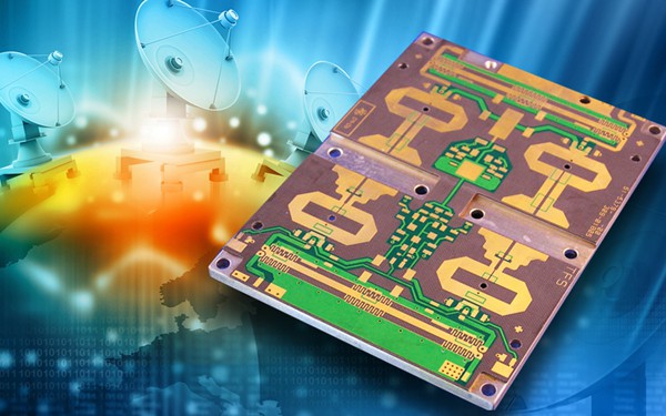
RF PCB & Microwave PCB, Rogers PCB -- Hitech Circuits Co., Limited
What is RF PCB & Microwave PCB?
RF PCB and microwave PCB are a type of printed circuit boards which carry the RF or microwave signal. So, these types of PCBs usually work on megahertz to gigahertz frequency ranges. Hence, we use these frequency ranges in communication technologies from mobile phones to military radars.
The materials used are advanced composites with very specific characteristics for dielectric constant (Er), loss tangent, and CTE (co-efficient of thermal expansion). These materials can be mixed in the same Stack-Up for optimal performance and economics.
The advantages of using materials with a low X, Y and Z CTE is a resulting PCB structure that will remain extremely stable in high temperature environments while operating at up to 40 GHz in analog applications, allowing for the effective placement of very fine pitch components including, in some cases, bare die-attach.
RF is Radio Frequency, a signal with a very high frequency. The choice of circuit board substrate depends on the requirements for the performance indicators of the circuit board. It can be ordinary FR4 epoxy glass fiber or a special microwave substrate such as Teflon, Arlon, Rogers materials.
As complexity of electronic components increases, the one thing that becomes imperative is signal rates and high frequency of transmission. Little surprise then that the demand for high frequency PCBs is on the rise. They find use in a variety of high-speed design applications that require a frequency range of 500MHz to 2GHz.

FR-4, based on epoxy resin and glass reinforcement, is the most popular laminate material for printed circuit board industry for a long time. The FR4 dielectric constant ranges from 3.8 to 4.8, depending on the glass weave style, thickness, resin content, and copper foil roughness. However, PCB industry also use other material for different application. In RF/microwave products, low loss and special controlled dielectric constant material like PTFE (Teflon) was widely used. These material was developed long time ago. Partly because of low volume in production, it is quite expensive in the past. When wireless became popular in consumer products years ago, the demand for low loss material was went high. But the material cost is still high. Even some new developed material were trying to get involved, it seems none of them can reduce the material cost dramatically. How to reduce the RF PCB cost became an essential problem for the designer. One of the solution is the mixed dielectric design.
Because the low loss material is not needed for all wireless system, it mostly designed-in, from my understanding, for the circuits from antenna to power amplifier. To reduce the PCB cost, designer used multiple PCB and only the front end of the receiver subsystem need high cost low loss material. However, the cost is still high because of multiple PCB’s and the connector between them. Beside, the Teflon PCB is soft and is comparably difficult in assembly due to warpage.
RF PCB standard:
1. Low power RF PCB mainly uses standard FR4 material (good insulation properties, uniform material, dielectric constant ε=4, 10%).
2. In the RF PCB design, each component should be closely arranged to ensure the shortest connection.
3. For a mixed-signal PCB, the RF and analog parts should be far away from the digital part (the distance is usually more than 2cm, at least 1cm), and the ground of the digital part should be separated from the RF part.
4. When selecting components to work in a high-frequency environment, use SMD(Surface Mounted Devices) as much as possible. SMD are small in size, and the component pins are generally very short.
This article provides guidelines and suggestions for radio frequency (RF) printed circuit board (PCB) design and layout, including some discussion of mixed-signal applications, such as digital, analog, and RF components on the same PCB. The content is organized by topic areas and provides “best practice” guidelines, which should be applied in conjunction with all other design and manufacturing guidelines. These guidelines may also apply to specific components, PCB manufacturers, and materials.
High Frequency PCB Features
1. The impedance control requirements are more stringent, the relative line width control is very strict, the general tolerance is about 2%.
2. Due to the special plate, the adhesion of PTH to copper is not high. It is usually necessary to roughen the via and surface by means of plasma processing equipment to increase the adhesion of PTH hole copper and solder resist ink.
3. Can not be used before the resistance welding, otherwise the adhesion will be very poor, can only be roughened with micro-etching water.
4. Most of the plates are made of PTFE. There are many burrs formed by ordinary milling cutters, and special milling cutters are required.
5. The high-frequency PCB is a special circuit board with a high electromagnetic frequency. Generally, the high frequency can be defined as a frequency above 1 GHz.
6. Its physical properties, precision, and technical parameters are very high, and it is often used in automotive anti-collision systems, satellite systems, radio systems and other fields.
7. In general terms, the PCB industry considers an RF circuit board to be any high frequency PCB that operates above 100MHz. Within the radio frequency class, anything above 2GHz is a Microwave PCB.
Benefits of RF PCB & Microwave PCB
1. RF circuit board and microwave PCB board can work on high Frequencies.
2. They have a stable structure. Hence, it allows them to work at high temperatures.
3. These have a stable dielectric constant and a low loss tangent. So, the signal travels through them with minimum impedance.
4. It is possible to form a multilayer board stack up. Hence, we can make smaller boards. Therefore, they give optimal performance and are cost-effective.
5. They allow for fabricating complex layouts. So, it is easier to assemble fine pitch components onto the board.
https://www.hitechpcba.com/rf-pcb-microwave-pcb
https://hitechcircuits.com/pcb-products/high-frequency-pcb/
https://www.hitechpcba.com/rogers-pcb
